Cellular analysis chip
Since 2003, this group was devoted to a new microfluidic device. A non-invasive hydrodynamic trapping method for bio-particles in a microfluidic device was presented. Lorentz-force-based resonating device was utilized to generate counter-rotating microvortices (CRMV) and to trap the bioparticles. The specific flow patterns earlier discovered demonstrates a flexible platform for cells trapping. Suspended particles passing above the oscillator can be trapped by CRMV without any solid contact. By adjusting the background flow velocity and drive voltage, the force required to trap and release of the particle is quantified. The trapping force is in pico-Newton range, and the maximum trapping force was investigated to be 12 ± 2.0 pN. Temperature increases around the fluid of the CRMV were noticed by using a temperature-dependant fluorescent dye, Rhodamine B for characterization. HEK-cells were also hydrodynamically trapped and shown to be viable after 30 minutes. Experimental results also confirmed the abilities of the new device on nanometer-length scale bio-particles, performing enrichment of antibodies in a low concentration PBS buffer flow. This hydrodynamic approach not only provides a gentle and harmless environment for cells but also feasible to perform pre-concentration of bio-molecules.
Particles Trapping
Trapping of suspended cells is fundamentally important for cellular studies. Some have utilized hydrodynamic approaches, particularly vortical flow. This work presents an entirely new device leveraging on a pair of counter-rotating micro-vortices to trap bio-particles. In contrast to other approaches, this device allows bioparticles to flow freely through unobstructed region, trapped, and controlled released. The authors believe this to be the first account of having these features.
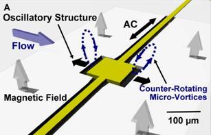 Figure 1. Sketch of the device. (A) The suspended thin (1μm thick) square plate (100μm*100μm) in resonance (140kHz.) induced a pair counter-rotating micro-vortices at plate edges. The total length of the suspended beam is 750μm and the width is 20μm. (B) Edge-on view of the oscillatory structure.
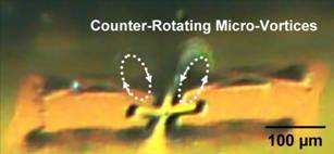 Figure 2. Micrograph of counter-rotating micro-vortices above the two-edges of the structure at resonant (140 kHz) at an instant in time. Trapped particles in the right vortex is evident. Left vortex also trapped particles as clearly seem in the movie. (Dotted lines are to guide the eyes.)
Chip Assembly
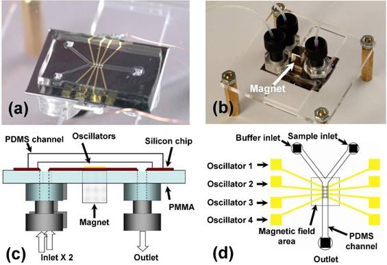
Figure 3. Microfluidic device. (a) There are four oscillators in a silicon chip (28mm*20mm) bonded in-between a PDMS channel and PMMA substrate (50mm*50 mm). Two wires were clipped to the metal pad for electric connection to the oscillators. (b) Device was upside down with tubing. A permanent magnet was placed right above the oscillator pierced through the PMMA substrate. (c) Schematic of device in cross-section. (d) A schematic of the microchannel with the four oscillators. The trapping region was in the middle of the channel and above the magnetic-field area marked by gray dotted line.
Bioparticels Trapping
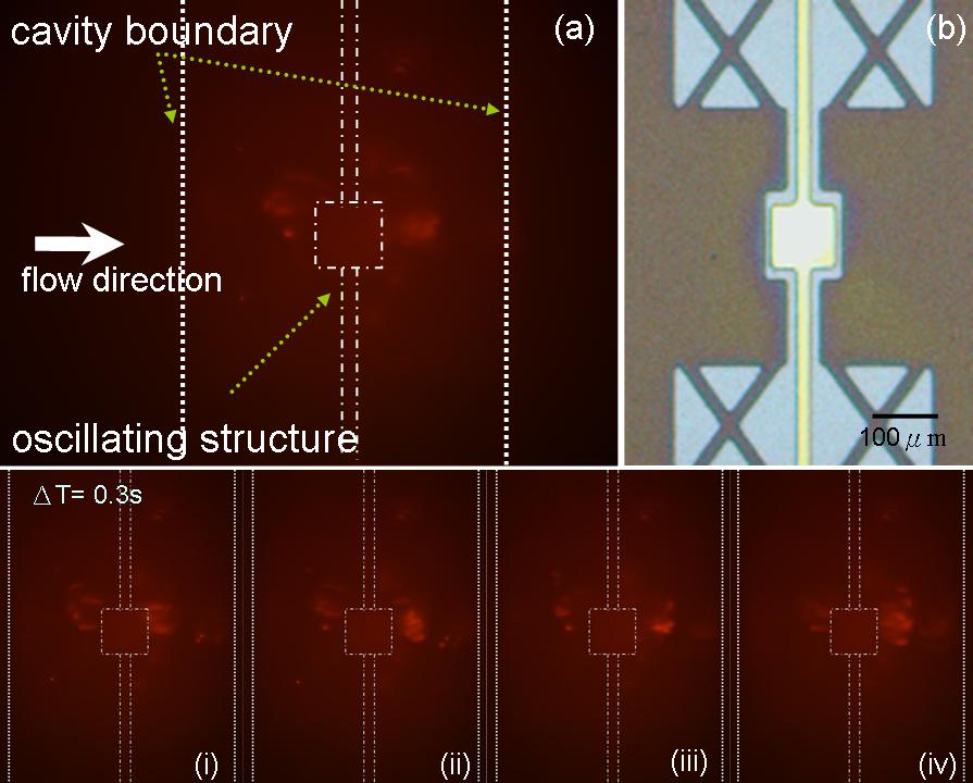
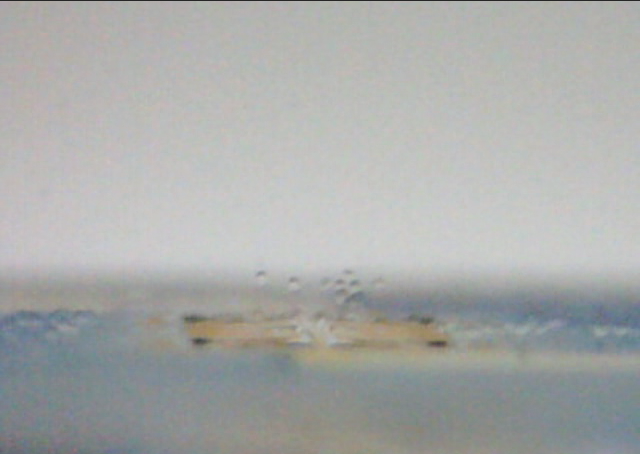
Figure 4 . (a) Shows the flow carrying proteins marked with fluorescent dye; proteins were trapped by vortices induced by the micro oscillating structure. (b) Top view from optical microscope. (i)~(iv) shows proteins were trapped and rotating above the oscillating structure at a time step, Δt = 0.3 second.
Cells Trapping
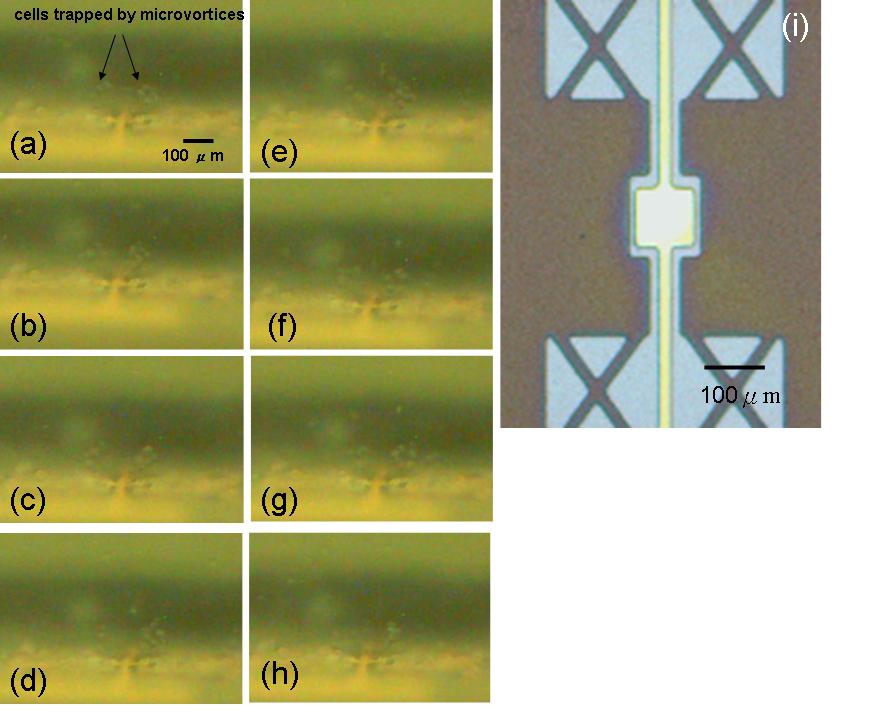
Figure 5. (a)~(h) show that CHO cells trapped and rotating above the oscillating structure at a time step, Δt = 0.5 second
HEK-Cells Trapping Experiment
Cell Vailbility Test
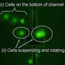
Figure 6. The cell viability of trapped HEK cells at 30min. (at 3Vpp, perfused at 20μm/s) Calcein AM was injected into channel for viability assay while cells trapped after 30min. White dash lines show the suspended plate. In upper left region (i), there are three bright green fluorescent marked cells are adhered on the bottom of channel. Clusters of HEK, in region (ii), cells rotating and trapped by the CRMV, there is no obvious difference between those two groups of cells. All of them were stained positively with calcein AM which demonstrates cells, in (b), are alive after continuous trapped by CRMV.
Rapid Micromixer
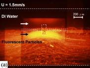
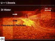
Figure 7. Mixer tested with 0.9μm fluorescent particles under an inverted microscope. (a) no signal was applied to the electrode, with the boundary of two flows evident. In (b) a sinusoidal signal of 90 kHz and 10Vp-p resulted in micro-vortices of Fig. 2. The thin plate and channel are denoted by dash line. (middle plate is 100μm by 200μm)
Relative Research Results
- 第四屆上銀科技台灣機械碩士論文獎 優等獎
- 台灣與美國專利
SCI Papers
- Cheng Ming Lin, Yu Shang Lai, Hsin Ping Liu, Andrew M. Wo*, “Microvortices and Recirculating Flow Generated by an Oscillatory Microplate for Microfluidic Applications” Applied Physics Letters, Vol. 93, Issue 13, 133503, 2008. (SCI 3.596)
- Cheng Ming Lin, Yu Shang Lai, Hsin Ping Liu, Chang Yu Chen, and Andrew M. Wo*, “Trapping of Bioparticles via Microvortices in a Microfluidic Device for Bioassay Applications,” Analytical Chemistry, 2008. (in press, SCI 5.287)
Conference Papers
- C. M. Lin, Y. S. Lai, H. P. Liu, and A. M. Wo, 2007 "Cell Trapping via Counter-Rotating Micro-Vortices," in The 11th International Conference on Miniaturized Systems for Chemistry and Life Sciences (MicroTAS) Paris, France.
- C. M. Lin, Y. S. Lai, H. P. Liu, and A. M. Wo, 2007 "Integration of a Micromixer and Tweezers for Cells and Bio-molecules Assay in a Microchannel," in IEEE-NANOMED Macau.
- H. P. Lui, C. M. Lin, Y. S. Lai, and A. M. Wo, 2008 "Mixing in a microfluidic device via rotating flow," in Nano and Micro Heat Transfer Tainan, Taiwan.
- C. M. Lin, C. C. Tseng, C. L. Chen, and A. M. Wo, 2009 "Hydrodynamic single-cell Trapping for celluar assays," in Transducers Denver, USA.
- C. M. Lin, C. C. Tseng, C. L. Chen, and A. M. Wo, 2009 "Hydrodynamic well for single-cell trapping in a microfluidic device," in The 13th International Conference on Miniaturized Systems for Chemistry and Life Sciences (MicroTAS) Jeju, Korea.