Chapter 7 Inductance
Contents
- Faraday's law of inductance
- Inductance
- Self-inductance
- Mutual inductance
- Inductors and RL circuits
- Power and energy stored in a magnetic field
- Exercises
$\S$ Faraday's law of inductance
Origin of electromagnetic inductance, and Lenz's law
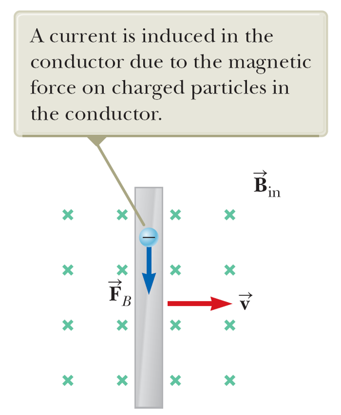 When a rod moves sideways cutting magnetic field lines, the charges experience the Lorentz force and accumulate at the ends of the rod, building an electric field that introduces a voltage difference across the rod. The Lorentz force must be balanced by the induced electric force.
\begin{equation}
qvB=qE=q\frac{V}{L}
\end{equation}
where $L$ is the length of the rod. Then we get the magnitude
\begin{equation}
V=vBL=\frac{\Delta x}{\Delta t}BL=\frac{\Delta \Phi_B}{\Delta t}.
\end{equation}
When a rod moves sideways cutting magnetic field lines, the charges experience the Lorentz force and accumulate at the ends of the rod, building an electric field that introduces a voltage difference across the rod. The Lorentz force must be balanced by the induced electric force.
\begin{equation}
qvB=qE=q\frac{V}{L}
\end{equation}
where $L$ is the length of the rod. Then we get the magnitude
\begin{equation}
V=vBL=\frac{\Delta x}{\Delta t}BL=\frac{\Delta \Phi_B}{\Delta t}.
\end{equation}
Lenz's law
In a loop enclosing a magnetic field, a current is induced such that it creates a magnetic field that opposes the change of the magnetic flux enclosed.
For a moving wire, a current is induced such that it experiences a magnetic force that opposes its motion in the rest frame of the magnetic field.
Magnetic flux
Magnetic flux is defined as $d\Phi_B=\vec B\cdot d\vec a$. The total flux enclosed by a loop is then\begin{equation} \Phi_B=\oint_S \vec B\cdot d\vec a \end{equation}
Unit: 1 Wb (weber)=1 T$\cdot$m$^2$.
Faraday's law of inductance
\begin{equation} V_{emf}=\oint_C \vec E\cdot d\vec l=-\frac{d\Phi}{dt}. \end{equation}The minus sign reflects Lenz's law such that the induced emf opposes the change of the magnetic flux, whose direction is determined by the right-hand rule.
Examples:
- Conducting rail
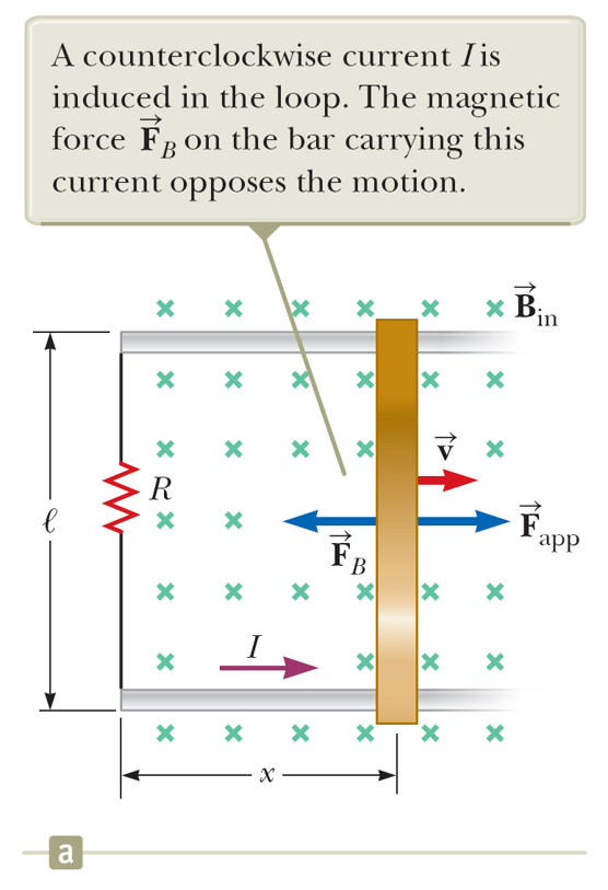
The magnetic flux is $\Phi_B=Blx$, pointing into the paper.
The emf induced is $\mathcal E=-\frac{d\Phi_B}{dt}=Blv$. The magnetic flux pointing into the paper (clockwise according to the right-hand rule) is increasing. The minus sign means to oppose its increase so an emf is induced to create a current $I=\mathcal E/R=\frac{Blv}{R}$ flowing counter-clockwise.
When carrying a current $I$, the Lorentz force on the moving rod is $F_B=IlB=\frac{B^2l^2v}{R}$. To keep the moving speed steady, an additional force $F_{app}$ needs to be applied to balance with $F_B$.
Thus the mechanical work done by $F_{app}$ is $P=F_{app}v=\frac{B^2l^2v^2}{R}$, which is exactly identical to the power dissipated by the resistor $P_R=I^2 R$.
- Rotating metal rod of angular frequency $\omega$

How to find the emf induced between two ends of the swiping metal rod?
Sol: Consider a small segment $dr$, whose speed is $v=r\omega$. According to the Faraday's law: $d\epsilon=Bvdr=Br\omega dr$, then \begin{equation} \mathcal E=\int_0^l B\omega r dr=\frac{1}{2}B\omega l^2 \end{equation}
- Electric generator
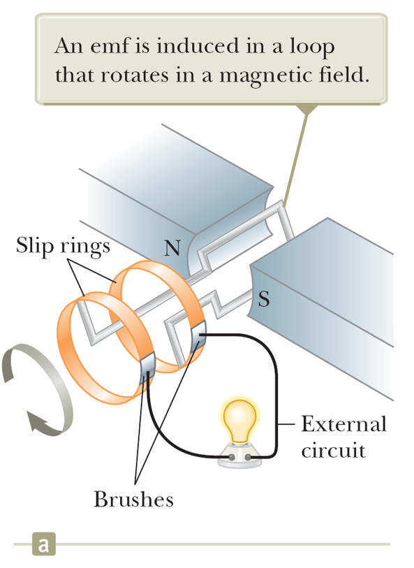
An electric generator is a device that converts mechanical work into electric energy in terms of emf and currents.
Assume that the B-field is uniform. The magnetic flux is then $\Phi_B=BA\cos\theta$ passing through each loop, where $\theta=\omega t$ is the angle between the normal area vector $\vec A$ and $\vec B$ with $\omega$ is the rotating angular frequency of the rectangular coil.
Then the emf is \begin{equation} \mathcal E=N BA\omega\sin\omega t. \end{equation}
Note that the maximal emf happens when $\theta=\pi/2$ and $3\pi/2$, where the effective flux is around 0.
$\S$ Inductance
In general, the inductance $L$ is defined as the proportion factor between magnetic flux and current: \begin{equation} \Phi_B=LI. \end{equation}
If the magnetic flux $\Phi_B$ is created passing through a loop carrying the current $I$, the inductance is called self-inductance.
VERY IMPORTANT!! If the inductance of a single loop is $L$, for a loop of $N$ turns, the overall self-inductance is NOT $NL$ but $N^2 L$ because the magnetic flux produced by each turn overlaps entirely. To be more explicit, if the loop has $N$ turns, the magnetic flux $\phi_b$ due to each turn adds up. This means the flux passing through every single turn of the loop is actually is $N\phi_b$. To count the TOTAL flux enclosed by all the $N$ turns, it should be $\Phi_B=N\times (N\phi_b)=N^2 L I$. So the overall inductance is $N^2 L$. (This is the most tricky part in this chapter.)
The strategy to calculate the self-inductance is (1) to identify the loop (2) to compute the magnetic field and then the flux passing through the loop, (3) and finally, divide the flux by the current.
Unit: The SI unit of inductance is H (Henry)=V$\cdot$s/A.
Examples
- Cable geometry
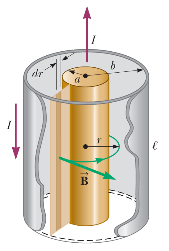
The magnetic field between the shell and the core is $B=\frac{\mu_0 I}{2\pi r}$. So that the flux is \begin{equation} \Phi_B=\int_a^b \frac{\mu_0 I}{2\pi r}ldr=\frac{\mu_0 Il}{2\pi}\ln \frac{b}{a}. \end{equation} The self-inductance per unit length is $L/l=\frac{\mu_0}{2\pi}\ln \frac{b}{a}$.
- Infinitely long solenoid
The magnetic field inside a solenoid is $B=\mu_0 n I$ with $n$ the density of turns. For a segment of length $l$, the number of turns is $N=nl$, and the total flux is $\Phi_B=\mu_0 n I a\times nl$. So the self-inductance per unit length is $L/l=\mu_0 n^2 a$ with $a$ the crosssection of the solenoid. Therefore, for a solenoid inductor of finite length $l$ and $N$ turns, the inductance can be approximated by $L=\mu_0 n^2 l a=\mu_0 N^2 a/l$.
- Two infinitely long parallel wires (Your exercise).
If a current creates magnetic flux that passes through another loop, the inductance is called mutual inductance. Suppose there are two loops $S_1$ and $S_2$. The mutual inductance (induction happening in $S_2$ due to current in $S_1$) is defined \begin{equation} M_{21}=\frac{\Phi_{21}}{I_1} \end{equation}
For a given arrangement, it can be proven that $M_{12}=M_{21}$. (Not trivial though.)
For the same arrangement, making $S_1$ of $N_1$ turns and $S_2$ of $N_2$ turns results in an inductance of $N_1 N_2$ times larger than the original one.
Example
Consider a large solenoid $S_1$ of crosssection $a$, length $L_1$, and $N_1$ turns enclosing a small solenoid $S_2$ of crosssection $b$, length $L_2$, and $N_2$ turns. Note here $a>b$ and $L_1\gg L_2$. Find the mutual inductance.
Sol: One can find the mutual inductance by looking at the magnetic flux due to $S_1$ (with current I) passing through $S_2$. The field is $B=\mu_0 I N_1/L_1$ and the total flux passing through $S_2$ is $\Phi_{21}=Bb\times N_2=\mu_0 I N_1 N_2 b/L_1$. So that $M=\mu_0 N_1 N_2 b/L_1$.
$\S$ Inductors and RL circuits
A device with a finite inductance is called an inductor. The symbol is

Note that the inductor has the following V-I relation \begin{equation} V_L=L\frac{dI}{dt}. \end{equation} (Keep in mind how the current direction is defined in the relation. There is no minus sign. Why?)

It is a bit subtle to consider inductors in parallel and in series because the magnetic flux created in one inductor may also contribute to others (the origin of mutual inductance). If there is no mutual inductance, we have $L=\sum_i L_i$ for inductors in series and $L^{-1}=\sum_i L_i^{-1}$ in parallel.
RL circuits
Examples
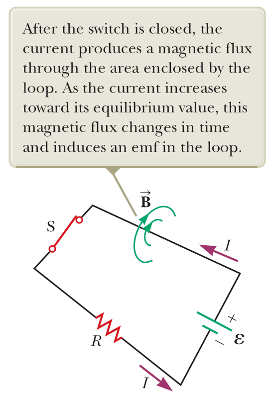
- Series combination of a resistor and an inductor

Sol: Applying Kirchhoff's loop rule, we find \begin{equation} V_{emf}=L\frac{dI}{dt}+IR \end{equation} and its solution is \begin{equation} I(t)=I(\infty)(1-e^{-t/\tau}) \end{equation} with the time constant $\tau=L/R$ and $I(\infty)=\frac{V_{emf}}{R}$. And \begin{equation} V_L(t)=V_{emf}e^{-t/\tau}. \end{equation}
- parallel combination of a resistor and an inductor

Sol: Applying Kirchhoff's loop rule, we find \begin{eqnarray} V_{emf}&=&IR_1+V_L\\ V_L&=&L\frac{dI_L}{dt}\\ I&=&I_L+\frac{V_L}{R_2} \end{eqnarray} which lead to \begin{equation} \frac{dI_L}{dt}+\frac{R_{eff}}{L}I_L=\frac{R_{eff}V_{rmf}}{R_1 L} \end{equation} with $R_{eff}=\frac{R_1 R_2}{R_1+R_2}$. The solution then reads \begin{equation} I_L(t)=I(\infty)(1-e^{-t/\tau}) \end{equation} with the time constant $\tau=L/R_{eff}$ and $I(\infty)=\frac{V_{emf}}{R_1}$. And \begin{equation} V_L(t)=\frac{R_2}{R_1+R_2}V_{emf}e^{-t/\tau}. \end{equation}
$\S$ Power and energy stored in a magnetic field
You can consider an inductor is a device that stores energy in the form of magnetic field (magnetic flux), analogous to a capacitor, who stored energy in the form of electric field (charge).
The energy stored in an inductor can be calculated through $\int P dt=\int LIdI=\frac{1}{2}LI^2=\frac{1}{2}I\Phi=\frac{\Phi^2}{2L}$.
Take a long solenoid of length $l$ as an example. The B-field is $B=\mu_0 N I/l$ and the inductance per unit length $L=mu_0 N^2 a/l$. Then the energy is \begin{equation} E_B=\frac{1}{2l}\mu_0 N^2 aI^2=\frac{1}{2}\frac{B^2}{\mu_0}\times al. \end{equation} Note that $al$ is the enclosed volume of the solenoid.
Then we can define an energy density \begin{equation} u_B=\frac{B^2}{2\mu_0} \end{equation} and $E_B=\int u_B(\vec r)d^3 x $.