NTU-Array

NTU-Array Project:
The coherent detector technology has been around for several decades in Radio Astronomy. It measures the electric field of incoming EM waves from the sky and takes advantage of the phase coherence of these waves for construction of the sky image with the Aperture Synthesis technique. One famous example of coherent detector instruments is the Very Large Array (VLA) of New Mexico, US, which appears in the movie “Contact”, in which Jodie Foster casted as a VLA astronomer.
The coherent detector technology is currently under rapid advancement, thanks to the technology drive of commercial 3G and 4G cellular phones. On one hand, cellular phones adopt a similar principle as a radio telescope to receive signals. On the other hand, cellular phones are highly integrated devices, with the so called system-on-chip (SOC) technology so as to make complex circuitry very compact.
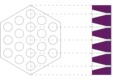
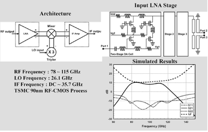
Our on-going hardware project for the Extended-NTU-Array is to install highly compact electronic devices into every receiver so that there can be as many as 19 identical small receivers (or pixels) within one big receiver. This widens the telescope field of view by a factor of 19 in comparison with the conventional single-pixel receiver adopted for the present NTU-Array. We are collaborating with electrical engineering teams from Chiao-Tung U., Taiwan U., and Taipei Institute of Science &Technology for this multi-pixel receiver project. NTU/Astrophysics is responsible for receiver and optics designs as well as the backend electronics, and the EE teams are in charge of developments of specific chips and packaging. As examples of these efforts, the schematics of the 19 feeds in the big receiver is shown in Fig.(1), and a RF mixer SOC is given in Fig.(2).
Fig.(1): Schematics of the 19-feed arrangement to be made by stacking several tens of copper slices.
Fig.(2): An example of SOC chip for the RF mixer that incorporates the components of upper left cormer.
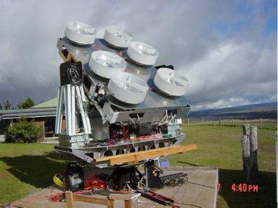
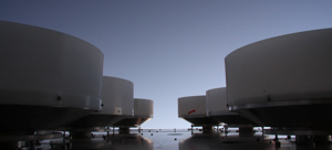
The current NTU-Array is a conventional interferometer telescope, like VLA, but with a much smaller size (Fig.(3)). The reason for it to be small is that this array is to measure fluctuations in the microwave background radiation of several arc-minute scale, and has been optimized for this angular scale. The array is equipped with six sets of 60cm antennae on a platform of 1.5x2.5 meter, it adopts digital correlation for backend signal processing, and most remarkably it receives sky signals from 78Ghz to 112Ghz, being a telescope covering the widest simultaneous bandwidth in the world. To handle the vast amount of data, the backend digital signal processor is also among the world most advanced electronic instruments in Radio Astronomy. It has an aggregate IO bandwidth of 4Tbps and a computational power 40tips (tera instructions per second), and amazingly this device consumes less than 1KW power. NTU Array was designed and integrated by a Taiwanese team led by NTU/Astrophysics. The telescope is presently located in the suburb of Las Vegas, Nevada, US, and expected to enter its routine observation phase any time.
Fig.(3): 6-Receiver NTU-Array. The antenna dish is 60cm in diameter and is of Cassegrain type. The received signals are transmitted through optical fibers to the control room behind the bush on the left for further digital processing.
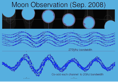
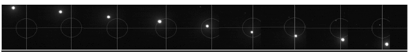
Fig.(4): Moon fringes when the Moon made a transit across the sky while the telescope remains standing still. Different fringe traces correspond to those produced by different frequency channels, and these fringes are almost in phase so that they can be co-added to enhance the signal-to-noise ratio. NTU-Array has 128 frequency channels that simultaneously cover 34Ghz.
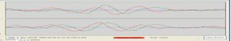
Fig.(5): Jupiter fringes of two frequency channels when Jupiter transits across the telescope field of view. The green and red fringe traces are the real and imaginary parts of a fringe, and are supposedly 90 degree out of phase as shown in this figure.
A number of tests have been carried out during our first-light observations. Shown in Fig.(4) is the interference fringe of the Moon when it passed across the field of view. Figure (5) shows the interference fringes of the much weaker Jupiter. From these fringe tests, we can understand how well the system performs and where the telescope needs to be tuned for optimization. More information can be found in the presentations at the following links.
1. 17.4GHz Ultra-wideband Digital Correlator in NTU-Array [PDF]
-
2.NTU-Array: Secondary CMB Anisotropy [PDF]
-
3.Effects of Nonuniform Input Spectra on Signal-to-Noise Ratio in Wide-Bandwidth Digital Correlation [PDF]