Chapter 10 Wave optics
In this chapter, Some of figures and materials, if not found in Serway's textbook, can be found in Benson's textbook of University Physics, especially the discussion in the section Grating and phasor analysis. (Don't worry. The phasor analysis discussed in this chapter belongs to optional advanced topics and will NOT be included in the exam.)
Contents
- Interference and Young's double slit experiment
- Change of phase due to reflection
- Interference in thin films
- Diffraction
- Resolution of single-slit and circular apertures
- Grating
- Exercises
$\S$ Interference and Young's double slit experiment
Wave optics is a study concerned with phenomena based on the wave nature of light. These phenomena include interference and diffraction. The most fundamental principle is Huygen's principle.
Interference: Constructive (destructive) interference happens when the superposed amplitude of the resultant wave is greater (less) than that of either individual wave.
To observe interference in light waves, the following two conditions must be met: (1) The sources should be monochromatic (Monochromatic means they have a single wavelength). (2) The sources must be coherent (They must maintain a constant phase with respect to each other).
Young's double-slit experiments
Thomas Young first demonstrated interference in light waves from two sources in 1801. The narrow slits, S1 and S2, act as sources of waves. The waves emerging from the slits originate from the same wave front and therefore are always in phase.
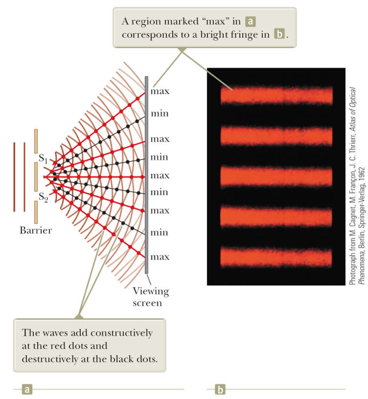
- The light from the two slits form a visible pattern on a screen consisting of a series of bright and dark parallel bands called fringes. Constructive interference occurs where a bright fringe occurs. Destructive interference results in a dark fringe.
Analysis
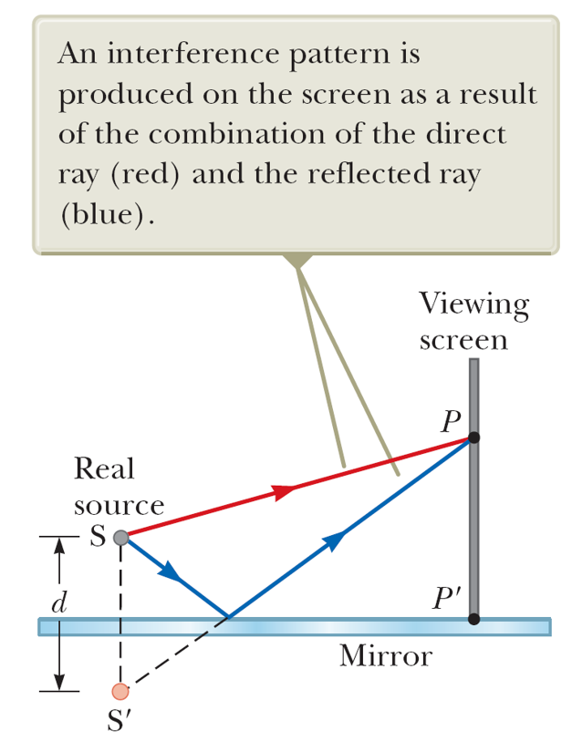
Consider a certain spot $P$ on the screen with distance $s_1$ to slit S1 and distance $s_2$ to slit S2. The signal (E-field) at $P$ at time $t$ must be $$ E(P,t)=E_1(t-s_1/c)+E_2(t-s_2/c) $$ where $E_1$ is the signal emitted from S1 and $E_2$ the signal emitted from S2. Suppose the signals coming out of S1 and S2 are in phase and of the form $E_{1,2}=E_0 \cos\omega t$. Also assume that the amplitude remains roughly constant. Set $t^\prime=t-s_1/c$ and $\Delta s=s_1-s_2$. Then $$ E(P,t)=E_0\cos(\omega t^\prime)+E_0\cos(\omega t^\prime+\omega\Delta s/c) $$ and the intensity $$ I_{int}\propto|E(P,t)|^2=|E_0|^2[\cos^2(\omega t^\prime)+\cos^2(\omega t^\prime+\omega\Delta s/c) +2\cos(\omega t^\prime)\cos(\omega t^\prime +\omega\Delta s/c)]. $$ Using the identity $2\cos\alpha\cos(\alpha +\beta)=\cos(2\alpha+\beta)+\cos\beta$, and taking the time average, we get $$ I_{ave}\propto|E_0|^2 \left(1+\cos\frac{\omega\Delta s}{c}\right)=2|E_0|\cos^2\frac{\pi d\sin\theta}{\lambda} $$ where $d$ is the separation of the two slits. For small $\theta$, we recover the formula that we have learned since high school: $$ I_{ave}=I_{max}\cos^2\frac{\pi d y}{\lambda L} $$ with $I_{max}$ the intensity of the brightest signal.
$\S$ Change of phase due to reflection
Refractive index: Recall the speed of light $c=\frac{1}{\sqrt{\epsilon_0 \mu_0}}$. In a medium, $\epsilon_0\rightarrow \epsilon$ but $\mu\approx \mu_0$. So the speed of light in the medium is $v=\frac{1}{\sqrt{\epsilon \mu_0}}$. Define the refractive index $\frac{n_1}{n_2}=\frac{v_2}{v_1}$. Since the speed of light in vacuum is the largest, the refractive index of vacuum is set to $n_{vac}=1$. The refractive index in air is approximately the same value as in vacuum.
Snell's law of refraction: $$ \frac{\sin\theta_1}{\sin\theta_2}=\frac{n_2}{n_1}. $$
An electromagnetic wave traveling from a medium of index of refraction n1 toward a medium of index of refraction $n_2$ undergoes a $\pi$ phase change on reflection when $n_2>n_1$. There is no phase change in the reflected wave if $n_2<n_1$.
Example
$\S$ Interference in thin films
The wavelength of light $\lambda_n$ in a medium with index of refraction $n$ is $$\lambda_n=\lambda/n.$$
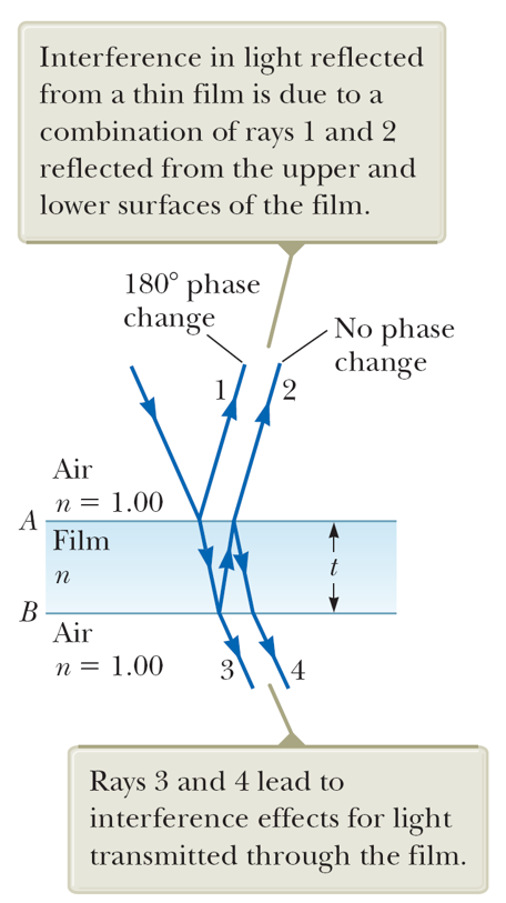
Now we assume that the light beam is incident normally ($\theta=0$) to a thin film of thickness $t$ while the both sides of the film contact with the air:
- Interference of Ray 1 & 2:
- Constructive: $2t=\left(m+\frac{1}{2}\right)\frac{\lambda}{n}$.
- Destructive: $2t=m\frac{\lambda}{n}$.
- Interference of Ray 3 & 4:
- Constructive: $2t=m\frac{\lambda}{n}$.
- Destructive: $2t=\left(m+\frac{1}{2}\right)\frac{\lambda}{n}$.
- Interference of Ray 1 & 2:
Example: Solar cell
Solar cells, devices that generate electricity when exposed to sunlight, are often coated with a transparent, thin film of silicon monoxide (SiO, n = 1.45) to minimize reflective losses from the surface. Suppose a silicon solar cell (n = 3.5) is coated with a thin film of silicon monoxide for this purpose. Determine the minimum film thickness that produces the least reflection at a wavelength of 550 nm, near the center of the visible spectrum.
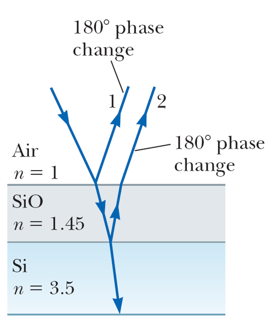
Sol:
Least reflection means destructive interference: Using the condition $2t=(m+1/2)\lambda/n$ with $\lambda=550$ nm. Set m=0 (minimal thicjness), we get $$ t=\frac{\lambda}{4n_{\text{SiO}}}=94.8 \text{(nm)}. $$
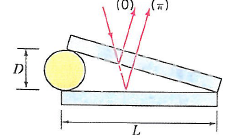
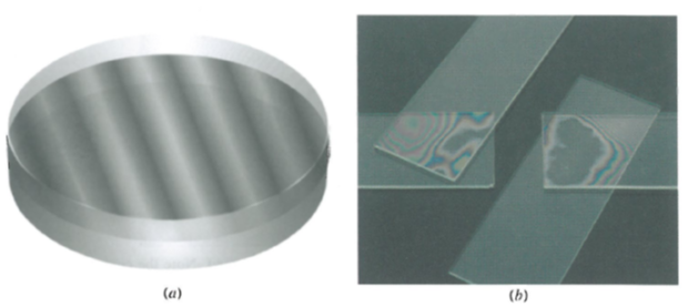
Example: Wedge-shaped air film
[Benson: University Physics]
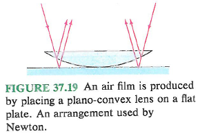
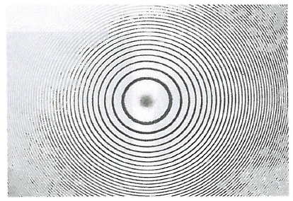
Example: Newton's ring
[Benson: University Physics]
$\S$ Diffraction
Review of materials about diffraction learned in high school
Mathematical theory of diffraction was developed by Fresnel.
Fresnel diffraction: When either the source or the screen is near the aperture or obstruction, the wavefronts are spherical and the pattern is quite complex. (near-field)
Fraunhofer diffraction: When both the source and the screen are at a great distance from the aperture or obstruction, the incident light is in the form of plane wave and the pattern is simpler to analyze. (far-field)
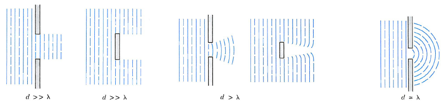
Diffraction and size effect
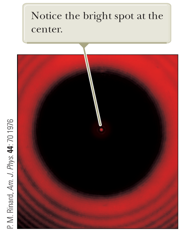
Arago bright spot (Poisson spot)
Formal derivation for single-slit diffraction:
Consider a single slit of breadth $a$. For analysis, we divide the breadth into infinitesimal segments with each located at $x$ relative to the center of the breadth. Suppose the signal (E-field) passing through a certain segment is $E=E_0\cos\omega t$, which is a function of $x$ and time. At a point P on the screen, the overall signal must be superposition of the individual signal from each segment of the slit. Therefore
$$
E(P,t)\propto\sum_x E\left(x,t-\frac{s}{c}\right)
$$
where $s$ is also a function of $x$.
The summation becomes an integral when the segment is infinitesimal:
$$
E\rightarrow \int_{-a/2}^{a/2} \cos\left(\omega t^\prime +\frac{\pi a}{\lambda}x\sin\theta\right)\propto \cos\omega t^\prime \frac{\sin(\pi a \sin\theta/\lambda)}{\sin\theta}\propto \cos\omega t^\prime\frac{\sin x}{x}
$$
with $x=\frac{\pi a}{\lambda}\sin\theta$.
Therefore, from $I_{ave}\propto|E_{ave}|^2$,
$$
I_{ave}=I_{max}\frac{\sin^2 x}{x^2}.
$$
The width of the central maximum in terms of span angle is $\lambda/a$.
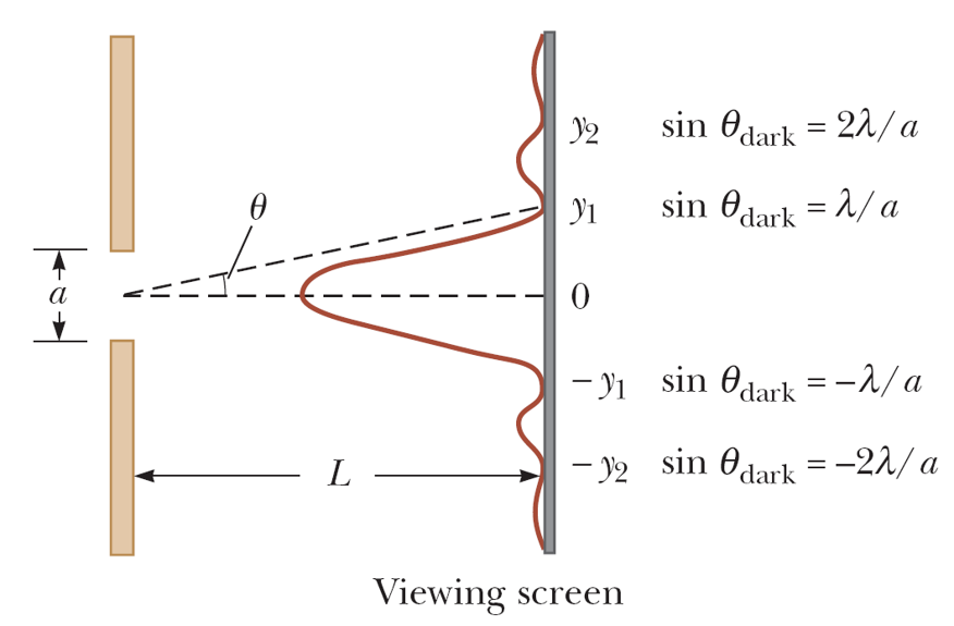
- A single slit placed between a distant light source and a screen produces a diffraction pattern: It will have a broad, intense central band, called the central maximum. The central band will be flanked by a series of narrower, less intense secondary bands, called side maxima. The central band will also be flanked by a series of dark bands, called minima.
$\S$ Resolution of single-slit and circular apertures
Suppose there are two objects which are being observed through a single slit. The resolution (the capability of distinguishing two close objects) is determined by the marginal condition that the center of the central peak of one object's image coincides with the boundary of the other object's image. This is called Rayleigh’s criterion.
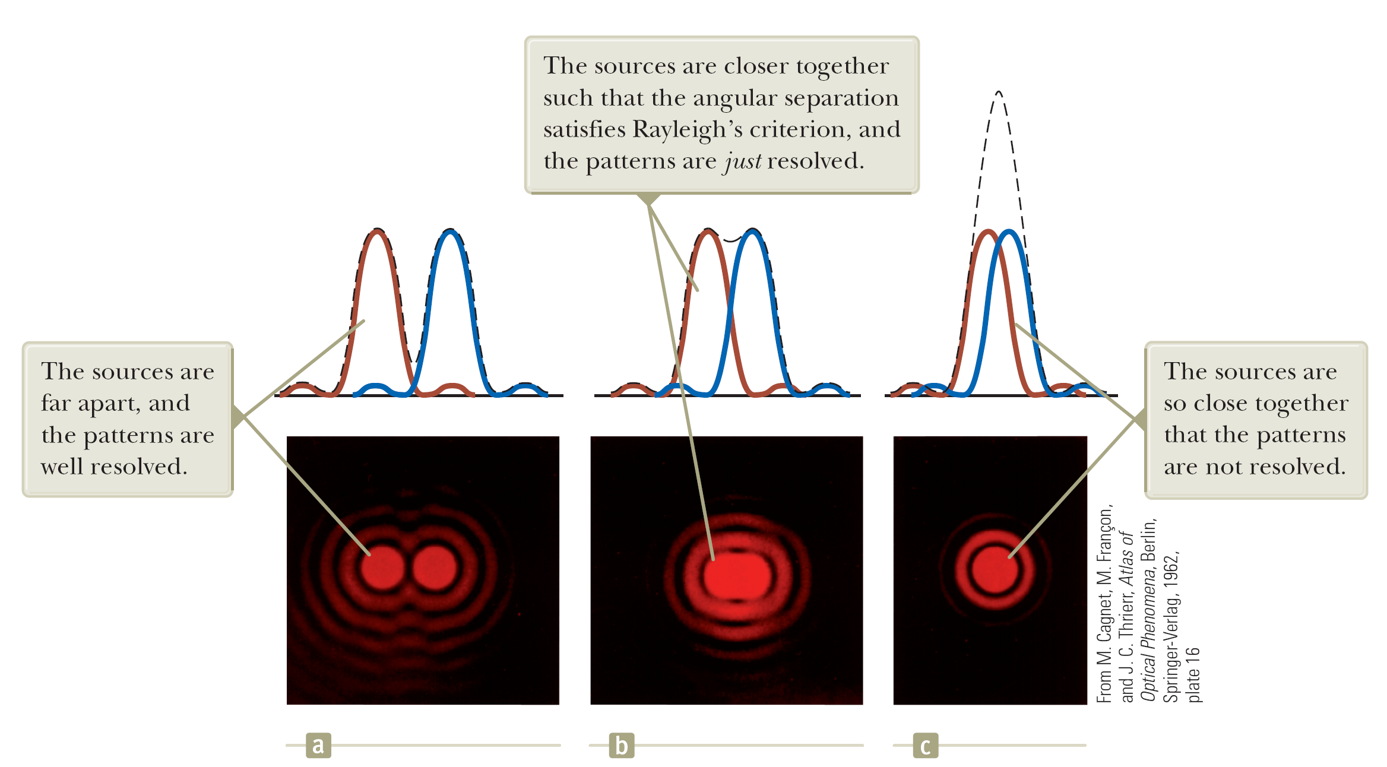
Therefore, the marginal span angle is $$\theta_{min} \approx \lambda/a.$$
The diffraction pattern of a circular aperture consists of a central bright disk surrounded by progressively fainter bright and dark rings. The limiting angle of resolution of the circular aperture is $$ \theta_{min}\approx 1.22\frac{\lambda}{D}$$ where $D$ is the diameter of the aperture.
$\S$ Grating
A diffracting grating consists of a large number of equally spaced parallel slits. A typical grating contains several thousand lines per centimeter.
The intensity of the pattern on the screen is the result of the combined effects of interference and diffraction. Each slit produces diffraction, and the diffracted beams interfere with one another to form the final pattern.
A transmission grating can be made by cutting parallel grooves on a glass plate. The spaces between the grooves are transparent to the light and so act as separate slits.
A reflection grating can be made by cutting parallel grooves on the surface of a reflective material.
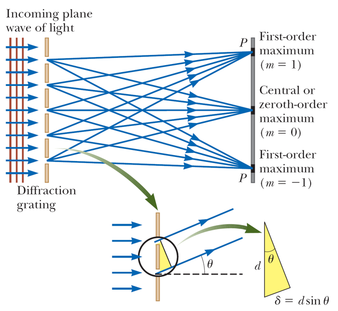
- Principal maxima: $d\sin\theta_{bright}=m\lambda$.
Phasor analysis [Benson: University Physics]
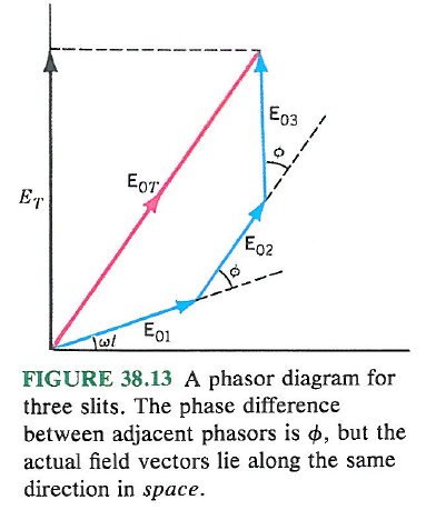
- In multiple-slit cases, we find the overall signal on a screen spot P is a superposition of all the contributions from each of the slit: $$ E_1=E_0\sin(\omega t)\\ E_2=E_0\sin(\omega t+\phi)\\ E_3=E_0\sin(\omega t+2\phi)\\ ... $$ where $\phi=\omega \Delta s/c=\frac{2\pi d\sin\theta}{\lambda}$ is the phase difference from adjacent slits. Now, we need to calculate $$E=E_1+E_2+E_3+\cdots$$ which can be dealt with by phasor analysis.
For example, for 3 equally spaced slits:
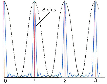
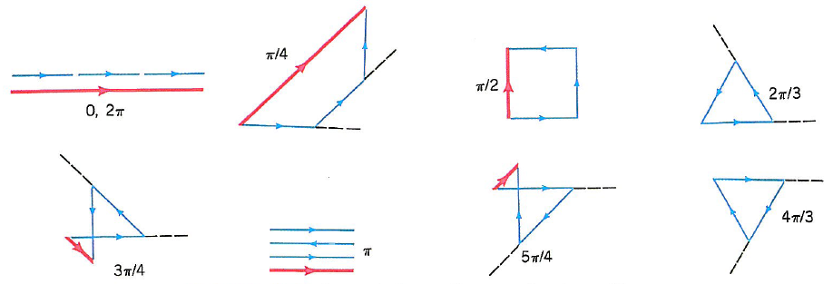
The principal maxima correspond to the phase $\phi$ such that the overall phasor $E$ is of the maximal magnitude. That is, $\phi=2m\pi$. This gives $d\sin\theta_{bright}=m\lambda$ for $m=0,1,2,\cdots$.
The minima correspond to the case that all the individual phasors add up to be 0. The phase $\phi=2m\pi/N$ where $m$ is an integer except for a multiple of $N$.
Revisit: Single-slit diffraction
- A single-slit can be seen as an infinite ($N\rightarrow\infty$) series of slits closely located that form an opening of breadth $a$. The total phase difference is $N\phi\rightarrow \alpha=\frac{2\pi a \sin \theta}{\lambda}$.
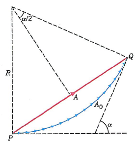
All the infinitesimal phasors add up to a total phasor. Suppose the arc length of the total phasor is $A_0$. The maxima corrspond to $\alpha=0$.
For arbitrary $\alpha$, one can find the magnitude of the total phasor $$ A=2R\sin\frac{\alpha}{2} $$ where $A_0=R\alpha$. Then we get the intensity $$ I=|A|^2=I_0\frac{\sin^2 (\alpha/2)}{\alpha^2/4}. $$
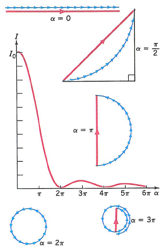
- The positions of secondary maxima correspond to $\alpha=2.86\pi$, $4.92\pi$, $6.94\pi$, $\cdots$, of intensity $0.047I_0$, $0.017I_0$, $0.008I_0$, $\cdots$.