Chapter 8 AC circuits
The materials in Ch 8 are not included in Serway's textbook, but are very important in the course of general physics. Please refer to other textbooks like Halliday's or Benson's. These materials will be included in the final exam.
Contents
- LC circuits
- RLC circuits
- Alternative current (AC) current and voltage sources: AC circuits
- Resistors in an AC circuit
- Capacitors in an AC circuit
- Inductors in an AC circuit
- Phasor and pictorial analysis
- Power and energy in AC circuits
- Transformers
- Exercises
$\S$ LC circuits
 Consider the above circuit, for which we have
\begin{eqnarray}
I&=&-C\frac{dV}{dt}\\
V&=&L\frac{dI}{dt}.
\end{eqnarray}
This leads to
\begin{equation}
\frac{d^2V}{dt^2}+\frac{1}{LC}V=0,
\end{equation}
whose solution is
\begin{eqnarray}
V(t)&=&V_m\cos (\omega t+\theta)\\
I(t)&=&C\omega V_m\sin (\omega t+\theta)
\end{eqnarray}
with $\omega=1/\sqrt{LC}$, and $V_0$ and $\theta$ are determined by initial conditions. This phenomenon is called LC oscillation.
Consider the above circuit, for which we have
\begin{eqnarray}
I&=&-C\frac{dV}{dt}\\
V&=&L\frac{dI}{dt}.
\end{eqnarray}
This leads to
\begin{equation}
\frac{d^2V}{dt^2}+\frac{1}{LC}V=0,
\end{equation}
whose solution is
\begin{eqnarray}
V(t)&=&V_m\cos (\omega t+\theta)\\
I(t)&=&C\omega V_m\sin (\omega t+\theta)
\end{eqnarray}
with $\omega=1/\sqrt{LC}$, and $V_0$ and $\theta$ are determined by initial conditions. This phenomenon is called LC oscillation.
Suppose at $t=0$, the charge on the capacitor is $Q_0$ on the upper side and there is no current. Then $V_m=\frac{Q_0}{C}$ and $\theta=0$.
$\S$ RLC circuits
Non-driven RLC circuit
 Consider the above circuit, and apply Kirchhoff's loop rule:
\begin{equation}
V_C+V_R+V_L=V_C+IR+L\frac{dI}{dt}=0
\end{equation}
and
\begin{equation}
I=C\frac{dV_C}{dt}.
\end{equation}
This leads to
\begin{equation}
\frac{d^2V_C}{dt^2}+\frac{R}{L}\frac{dV_C}{dt}+\frac{1}{LC}V_C=0.
\end{equation}
This is exactly the standard form of a damped oscillator: $\ddot V_C+\gamma \dot V_C +\omega_0^2 V_C=0$.
Consider the above circuit, and apply Kirchhoff's loop rule:
\begin{equation}
V_C+V_R+V_L=V_C+IR+L\frac{dI}{dt}=0
\end{equation}
and
\begin{equation}
I=C\frac{dV_C}{dt}.
\end{equation}
This leads to
\begin{equation}
\frac{d^2V_C}{dt^2}+\frac{R}{L}\frac{dV_C}{dt}+\frac{1}{LC}V_C=0.
\end{equation}
This is exactly the standard form of a damped oscillator: $\ddot V_C+\gamma \dot V_C +\omega_0^2 V_C=0$.
Underdamped behavior: $\omega_0>\gamma/2$
The solution is of the form: \begin{equation} V_C(t)=V_m e^{-\frac{\gamma}{2}t} \sin(\omega t+\phi) \end{equation} where $\gamma=R/L$ and $\omega=\sqrt{\omega_0^2-\gamma^2/2}$.
Overdamped behavior: $\omega_0<\gamma/2$
\begin{equation} V_C(t)=A_m e^{-\frac{\gamma_1}{2}t}+B_m e^{-\frac{\gamma_2}{2}t} \end{equation}where $\gamma_{1,2}=\gamma\pm\sqrt{\gamma^2-4\omega_0^2}$.
Critical behavior: $\omega_0=\gamma/2$
\begin{equation} V_C(t)=(A_m+B_m t) e^{-\frac{\gamma}{2}t}. \end{equation}Sinusoidally driven RLC circuit
See discussion for AC circuits below.
$\S$ Alternative current and voltage sources: AC circuits
There are two kinds of sources to help our analysis for AC circuits: current and voltage sources. $$ V_S=V_0 \sin\omega t\\ I_S=I_0 \sin\omega t $$ Note that here we already set the phase $\theta=0$ for the source $\sin(\omega t+\theta)$. This is important as a phase reference. In the following analysis, every device can have a response with a relative phase angle to the reference.
Usually we will only have one source (either current or voltage) in an AC circuit.
Phase angle in the response
Since the most important property of a device is the I-V relation. Given the voltage source, the response is the current passing through it; given the current source, the response is the terminal voltage. For example, for a given voltage source $V_S(t)\propto\sin \omega t$, if a device's response is $I(t)\propto \sin(\omega t+\phi)$, we say that the current is ahead of the voltage by angle $\phi$ if $\phi>0$. If $\phi<0$, then the voltage is ahead of the current by $|\phi|$.
Resistors in an AC circuit
Resistors are the most "well-behaved" device where the voltage and current are proportional to each other with $\phi=0$: $$I(t)=\frac{V_0}{R}\sin\omega t.$$ We also call them in-phase.
$\S$ Capacitors in an AC circuit
Consider a sinusoidal voltage source $V_S$ directly connected to a capacitor $C$. Since we have $$I_C=C\frac{dV_S}{dt}=C\omega V_0\cos\omega t=C\omega V_0\sin\left(\omega t+\frac{\pi}{2}\right),$$ it means the current response is ahead of the voltage by $\frac{\pi}{2}$.
We define reactance $X$ as the ratio between the magnitude of $V_C$ and that of the current $I_C$: $$X_C=\frac{1}{C\omega}.$$ X has the same unit $\Omega$ (ohm) as resistance. It is called reactance because the voltage and current differ by $\frac{\pi}{2}$.
$\S$ Inductors in an AC circuit
Consider a sinusoidal current source $I_S$ directly connected to an inductor $L$. Since we have $$V_L=L\frac{dI_S}{dt}=L\omega I_0\cos\omega t=L\omega I_0\sin\left(\omega t+\frac{\pi}{2}\right),$$ it means the voltage response is ahead of the current by $\frac{\pi}{2}$.
We also define reactance $X$ as the ratio between the magnitude of $V_L$ and that of the current $I_S$: $$X_L=L\omega.$$
$\S$ Phasor and pictorial analysis
Here we introduce a very powerful tool called phasor analysis. It is commonly used in any system that has a fixed frequency for the source and responses. Then we can view things at a rotating frame of the particular frequency $\omega$.
The working principle behind the phasor analysis is the usage of Euler's formula $e^{i\theta}=\cos\theta+i\sin \theta$ and the two-dimensional complex space (plane): $$ \sin(\omega t+\phi)=Im(e^{i(\omega t+\phi)})\\ \cos(\omega t+\phi)=Re(e^{i(\omega t+\phi)}) $$
A phasor is a vector (on the complex plane) whose length is proportional to the maximum value of the variable it represents and which rotates counterclockwise at an angular speed equal to the angular frequency associated with the variable.
Example

In this circuit, the loop rule requires $V_S(t)=V_R(t)+V_L(t)+V_C(t)$ to be satisfied at all times. Note that the current $I(t)$ though the whole loop can vary in time, but must be identical everywhere because otherwise there should be accumulated net charges. (It is different from the stored charges on the capacitor because the net charge, positive + negative, is still zero.)
Suppose $I(t)=I_0 \sin\omega t$ (with the initial phase set to 0). From previous discussion, we know
For a resistor: the voltage and current are in phase so $V_R(t)=RI(t)=I_0 R \sin\omega t$.
For a capacitor: the voltage has a phase $\pi/2$ lag relative to the current so $V_C(t)=I_0 X_C \sin(\omega t -\pi/2)$.
For an inductor: the voltage has a phase $\pi/2$ ahead of the current so $V_C(t)=I_0 X_L \sin(\omega t +\pi/2)$.
Phasor analysis: Recall these sine functions can be obtained by taking the imaginary part of the exponential ones of the form $e^{i(\omega t+\theta)}$. Now, instead of working on these sine functions, let's work on the associated exponentials!!
For instance: Define a phasor $\mathbf{I}=I_0 e^{i\omega t}=I_0\cos \omega t +i I_0 \sin\omega t$. This corresponds to a vector $(x=I_0\cos \omega t, y=I_0 \sin\omega t)$ on a complex plane. When time evolves, the vector rotates at angular frequency $\omega$. When we want to obtain the physical value that makes sense, in this case we just need to take the imaginary part. (The real part here just plays an auxiliary role.)
We go on using the phasor notation for $V_R(t)$, $V_C(t)$, and $V_L(t)$:
Resistor: $\mathbf{V}_R=\mathbf{I}R$.
Capacitor: $\mathbf{V}_C=\mathbf{I}X_C e^{-i\pi/2}\equiv\mathbf{I}Z_C$. We define $Z_C=\frac{1}{i\omega C}$, called the impedance of $C$.
Inductor: $\mathbf{V}_L=\mathbf{I}X_L e^{i\pi/2}\equiv\mathbf{I}Z_L$. We define $Z_L=i\omega L$, called the impedance of $L$.
Then the loops rule becomes the phasor version: $$ \mathbf V_R+\mathbf V_L+\mathbf V_C=\mathbf I (R+Z_C +Z_L).$$ The effective impedance of the whole combination is $Z=R+i(X_L-X_C)\equiv |Z|e^{i\phi}$, where $|Z|=\sqrt{R^2+(X_L-X_C)^2}$, and $\phi=\tan^{-1}\frac{X_L-X_C}{R}.$ This angle characterizes by how much of the phase angle the voltage is ahead of the current.
Pictorial analysis
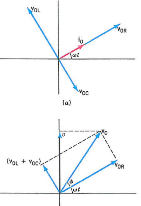
One can use the phasor diagram to help solve the problem (borrowed from Benson's book). Here, $X_L>X_C$; $i_0$ stands for the phasor $\mathbf{I}$; $V_{0R}$, $V_{0C}$, and $V_{0L}$ are phasors $\mathbf{V}_R$, $\mathbf{V}_C$, and $\mathbf{V}_L$, respectively. Then the addition law of vector applies here. The resultant phasor must be the same as the voltage phasor provided by the source. The actual value is just from taking the imaginary part (y-axis projection). Note that the angle $\phi>0$ indicates that the voltage is ahead of the current.
Note that the magnitude of a phasor is the peak value (amplitude) of the actual quantity. The Ohm's law still holds for the magnitudes: $$V_0=|\mathbf V_S|=|\mathbf I||Z|,$$ and further, \begin{eqnarray} \mathbf V_{R}&=&\frac{R}{Z}\mathbf V_S\\ \mathbf V_{C}&=&\frac{Z_C}{Z}\mathbf V_S\\ \mathbf V_{L}&=&\frac{Z_L}{Z}\mathbf V_S \end{eqnarray} so the rule of partial voltage still applies.
Now, as an example, we look at the actual voltage across the capacitor: $$V_{0C}=\frac{X_C V_0}{\sqrt{R^2+(X_L-X_C)^2}}=\frac{V_0 \omega_0^2}{\sqrt{R^2\omega^2/L^2+(\omega^2-\omega_0^2)^2}}.$$ When $R\rightarrow 0$, and as $\omega\rightarrow \omega_0$, $V_{0C}$ diverges.
Another example (your exercise)

$\S$ Power and energy in AC circuits
The instantaneous power output or consumed by a device is $P(t)=I(t)V(t)$. Suppose now the voltage is ahead of the current by a phase angle $\phi$, then $$P(t)=I_0 V_0 \sin \omega t \sin(\omega t+\phi)=I_0 V_0 \sin^2 \omega t \cos \phi.$$
We define its time average as the root-mean-square (rms) power $$P_{av}=\frac{I_0 V_0}{2} \cos\phi,$$ where $\cos\phi$ is called the power factor. Similarly, we define the rms voltage $V_{av}=V_0/\sqrt 2$ and current $I_{av}=I_0/\sqrt 2$ so $P_{av}=I_{av}V_{av}\cos\phi.$
Note that for capacitors and inductors, their power factor $\cos\theta=0$, meaning on average they will not output or consume energy.
$\S$ Transformer
A transformer has a primary coil with $N_1$ turns and a secondary coil with $N_2$ turns, ad two coils share a core that conducts the magnetic flux. For a perfect transformer, it obeys $$\frac{V_1}{N_1}=\frac{V_2}{N_2}=\frac{d\Phi}{dt}.$$ Due to energy conservation $I_1V_1=I_2V_2$, the currents obey $$N_1I_1=N_2I_2.$$